

简介
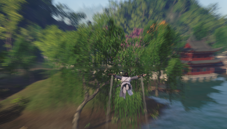
游戏都追求画面感,而个人感觉后处理是最有效的表现画面感的方式之一(虽然比较收费)。我以前玩过这种模糊效果。今天我来看看另一个模糊效果,径向模糊。这种效果对提高画面感非常有帮助,特别是在快速动作突然加速的瞬间,或是老板吼出来的画面效果。所以我第一次想到天涯明月刀的光影工作瞬间飞升加速,使用径向模糊使光影工作突然加速。
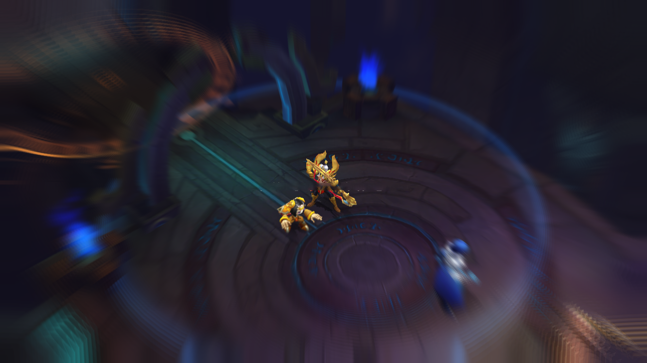
“王者的荣耀”也有径向模糊的效果。
径向模糊效果的原理
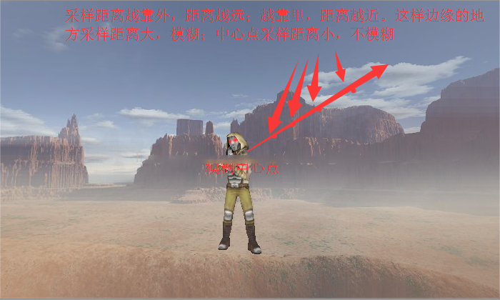
放射状模糊效果是后处理,后处理的原理不多,用描绘的屏幕图像进行全画面操作。首先,看图,从中心部分向外侧扩大,感觉画面向外延伸。因此,在fragment阶段,之前的文章为了在线效果的后处理时露出轮廓,可以使用模糊效果对像素和周围的像素进行加权平均这样的想法进行处理。另一方面,关于放射状模糊也一样,关于各像素点,虽然不一定是画面的正中心,自己可以指定)求出1个方向,从中心朝向该像素点的方向是放射状的模糊方向,其次是现在的像素点以及放射状。进一步将几个点作为抽样点取得,抽样点越靠近中心越紧密,变得疏松。最后,这个像素点的输出是这些抽样点的平均值。.像这样,在靠近中心点的位置,取样距离小,几乎为0。没有模糊,距离越近取样距离越大,图像变得模糊。
放射状模糊的原理如下.
径向模糊在Unity下的实现
了解原理后,我们在Unity下实现了1版放射状模糊效果.在后期处理的组合中,C#脚本部分RadialBlurEffect类继承了PostEffectBase类。这个等级在以前的报道中进行了说明,但是这里不显示。
RadialBlurEffect脚本:
using UnityEngine;

public class RadialBlurEffect : PostEffectBase {

    //模糊程度,不能过高
    [Range(0,0.05f)]
    public float blurFactor = 1.0f;
    //模糊中心(0-1)屏幕空间,默认为中心点
    public Vector2 blurCenter = new Vector2(0.5f, 0.5f);

void OnRenderImage (RenderTexture source, RenderTexture destination)
    {
        if (_Material)
        {
            _Material.SetFloat("_BlurFactor", blurFactor);
            _Material.SetVector("_BlurCenter", blurCenter);
            Graphics.Blit(source, destination, _Material);
        }
        else
        {
            Graphics.Blit(source, destination);
        }
}
}
RadialBlurShader1:
Shader "ApcShader/PostEffect/RadialBlurShader1"
{
Properties
{
_MainTex ("Base (RGB)", 2D) = "white" {}
}

CGINCLUDE
uniform sampler2D _MainTex;
uniform float _BlurFactor; //模糊强度(0-0.05)
uniform float4 _BlurCenter; //模糊中心点xy值(0-1)屏幕空间
#include "UnityCG.cginc"
#define SAMPLE_COUNT 6 //迭代次数

fixed4 frag(v2f_img i) : SV_Target
{
//模糊方向为模糊中点指向边缘(当前像素点),而越边缘该值越大,越模糊
float2 dir = i.uv - _BlurCenter.xy;
float4 outColor = 0;
//采样SAMPLE_COUNT次
for (int j = 0; j < SAMPLE_COUNT; ++j)
{
//计算采样uv值:正常uv值+从中间向边缘逐渐增加的采样距离
float2 uv = i.uv + _BlurFactor * dir * j;
outColor += tex2D(_MainTex, uv);
}
//取平均值
outColor /= SAMPLE_COUNT;
return outColor;
}
ENDCG

SubShader
{
Pass
{
ZTest Always
Cull Off
ZWrite Off
Fog{ Mode off }

//调用CG函数
CGPROGRAM
//使效率更高的编译宏
#pragma fragmentoption ARB_precision_hint_fastest
//vert_img是在UnityCG.cginc中定义好的,当后处理vert阶段计算常规,可以直接使用自带的vert_img
#pragma vertex vert_img
#pragma fragment frag
ENDCG
}
}
Fallback off
}
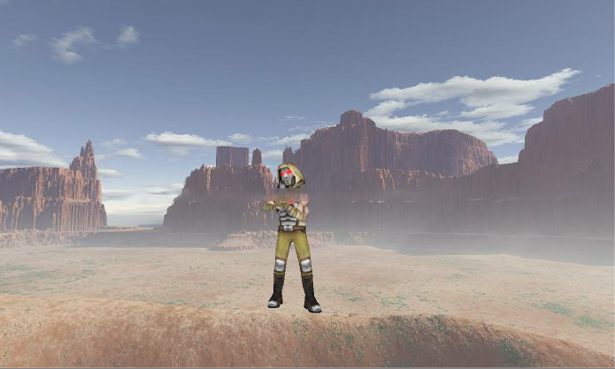
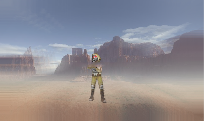
我们在寻找场景并测试其效果。以下是未启用“径向模糊”效果的原始场景。
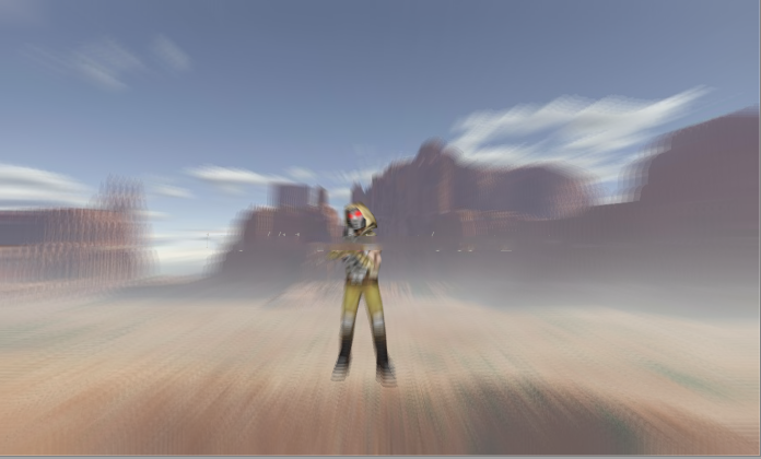
开启径向模糊效果后:
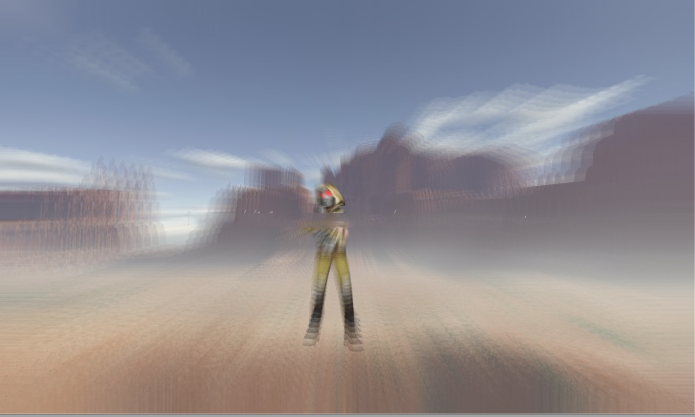
调整模糊强度:
径向模糊的优化
径向模糊和高斯模糊,均值模糊等模糊效果一样,都是采样次数越高,模糊效果越好,但是采样次数高了,性能就下去了,尤其是在移动设备上,GPU不强,但是分辨率极高,后处理这种全屏纹理采样及其耗费性能。所以,优化很重要。我们在高斯模糊以及Bloom效果中使用了降分辨率的操作,对于径向模糊,一样实用。优化的思路如下:首先,我们将图像渲染到一张降低了分辨率的RT上,然后使用这个降低了分辨率的RT进行上面的模糊处理;最后再将这个RT与原始图像进行插值操作。这样会多一个Pass(一个Draw Call),但是由于降低了分辨率,仍然对性能会有较好的提升。下面附上更改后的径向模糊代码。
RadialBlurEffect2脚本:
using UnityEngine;

public class RadialBlurEffect2 : PostEffectBase {

    //模糊程度,不能过高
    [Range(0,0.1f)]
    public float blurFactor = 1.0f;
    //清晰图像与原图插值
    [Range(0.0f, 2.0f)]
    public float lerpFactor = 0.5f;
    //降低分辨率
    public int downSampleFactor = 2;
    //模糊中心(0-1)屏幕空间,默认为中心点
    public Vector2 blurCenter = new Vector2(0.5f, 0.5f);

void OnRenderImage (RenderTexture source, RenderTexture destination)
    {
        if (_Material)
        {
            //申请两块降低了分辨率的RT
            RenderTexture rt1 = RenderTexture.GetTemporary(source.width >> downSampleFactor, source.height >> downSampleFactor, 0, source.format);
            RenderTexture rt2 = RenderTexture.GetTemporary(source.width >> downSampleFactor, source.height >> downSampleFactor, 0, source.format);
            Graphics.Blit(source, rt1);

            //使用降低分辨率的rt进行模糊:pass0
            _Material.SetFloat("_BlurFactor", blurFactor);
            _Material.SetVector("_BlurCenter", blurCenter);
            Graphics.Blit(rt1, rt2, _Material, 0);

            //使用rt2和原始图像lerp:pass1
            _Material.SetTexture("_BlurTex", rt2);
            _Material.SetFloat("_LerpFactor", lerpFactor);
            Graphics.Blit(source, destination, _Material, 1);

            //释放RT
            RenderTexture.ReleaseTemporary(rt1);
            RenderTexture.ReleaseTemporary(rt2);
        }
        else
        {
            Graphics.Blit(source, destination);
        }
}
}
RadialBlurEffect2.shader:
Shader "ApcShader/PostEffect/RadialBlurShader2"
{
Properties
{
_MainTex ("Base (RGB)", 2D) = "white" {}
_BlurTex("Blur Tex", 2D) = "white"{}
}

CGINCLUDE
uniform sampler2D _MainTex;
uniform sampler2D _BlurTex;
uniform float _BlurFactor; //模糊强度(0-0.05)
uniform float _LerpFactor;  //插值的强度(0-1)
uniform float4 _BlurCenter; //模糊中心点xy值(0-1)屏幕空间
float4 _MainTex_TexelSize;
#include "UnityCG.cginc"
#define SAMPLE_COUNT 6 //迭代次数

fixed4 frag_blur(v2f_img i) : SV_Target
{
//模糊方向为模糊中点指向边缘(当前像素点),而越边缘该值越大,越模糊
float2 dir = i.uv - _BlurCenter.xy;
float4 outColor = 0;
//采样SAMPLE_COUNT次
for (int j = 0; j < SAMPLE_COUNT; ++j)
{
//计算采样uv值:正常uv值+从中间向边缘逐渐增加的采样距离
float2 uv = i.uv + _BlurFactor * dir * j;
outColor += tex2D(_MainTex, uv);
}
//取平均值
outColor /= SAMPLE_COUNT;
return outColor;
}

//定义最后插值使用的结构体
struct v2f_lerp
{
float4 pos : SV_POSITION;
float2 uv1 : TEXCOORD0; //uv1
float2 uv2 : TEXCOORD1; //uv2
};
v2f_lerp vert_lerp(appdata_img v)
{
v2f_lerp o;
o.pos = mul(UNITY_MATRIX_MVP, v.vertex);
o.uv1 = v.texcoord.xy;
o.uv2 = v.texcoord.xy;
//dx中纹理从左上角为初始坐标,需要反向(在写rt的时候需要注意)
#if UNITY_UV_STARTS_AT_TOP
if (_MainTex_TexelSize.y < 0)
o.uv2.y = 1 - o.uv2.y;
#endif
return o;
}

fixed4 frag_lerp(v2f_lerp i) : SV_Target
{
float2 dir = i.uv1 - _BlurCenter.xy;
float dis = length(dir);
fixed4 oriTex = tex2D(_MainTex, i.uv1);
fixed4 blurTex = tex2D(_BlurTex, i.uv2);
//按照距离乘以插值系数在原图和模糊图之间差值
return lerp(oriTex, blurTex, _LerpFactor * dis);
}
ENDCG

SubShader
{
//Pass 0 模糊操作
Pass
{
ZTest Always
Cull Off
ZWrite Off
Fog{ Mode off }

//调用CG函数
CGPROGRAM
//使效率更高的编译宏
#pragma fragmentoption ARB_precision_hint_fastest
//vert_img是在UnityCG.cginc中定义好的,当后处理vert阶段计算常规,可以直接使用自带的vert_img
#pragma vertex vert_img
#pragma fragment frag_blur
ENDCG
}

//Pass 1与原图插值操作
Pass
{
ZTest Always
Cull Off
ZWrite Off
Fog{ Mode off }

//调用CG函数
CGPROGRAM
//使效率更高的编译宏
#pragma fragmentoption ARB_precision_hint_fastest
//vert_img是在UnityCG.cginc中定义好的,当后处理vert阶段计算常规,可以直接使用自带的vert_img
#pragma vertex vert_lerp
#pragma fragment frag_lerp
ENDCG
}
}
Fallback off
还是刚才的场景,使用新版本的后处理效果的结果如下:
这里我们降低了2倍分辨率,极大地降低了采样带来的消耗。虽然效果也打了些折扣,不过还是可以凑合看的,哈哈。
UNITY_UV_STARTS_AT_TOP宏
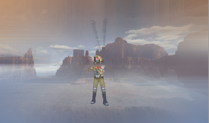
我们写后处理shader时经常遇到的一个问题就是有时候开启后处理效果时屏幕上下颠倒了(或者叠加上去的部分上下颠倒了),在之前的屏幕水波纹效果中就遇到了类似的问题。那么有时候是什么时候呢?需要满足几个条件,第一,使用DX渲染器时(也就是在PC平台);第二,开启了抗锯齿(AA);第三,开启了后处理并且在后处理中使用了除了MainTex外的屏幕RT(或者后处理中跟屏幕像素相关的值直接传入shader),比如上面的shader中我们除了MainTex外额外传入了一张BlurTex,我们仍然用MainTex的uv来处理时。同时满足了上面三点,就会出现屏幕上下颠倒的现象。如下图所示:
本人第一次遇到这个问题时瞬间想到《艾希》最后旁白的那段Boss战,旁白直接把屏幕倒转过来,在《地狱边境》中也有类似的上下颠倒的关卡。shader能做的东西好多,之前一直没想到过那种上下屏幕颠倒是怎么做的,再仔细一想,其实只要在正常做,增加一个后处理,把采样的uv的y坐标反过来,就可以了。
那么,为什么会出现这种屏幕翻转的问题,又为什么满足这几个条件才会有这种屏幕翻转的问题呢?引用一段官方文档上的解释:
Direct3D-like: The coordinate is 0 at the top and increases downward. This applies to Direct3D, Metal and consoles.OpenGL-like: The coordinate is 0 at the bottom and increases upward. This applies to OpenGL and OpenGL ES.This difference tends not to have any effect on your project, other than when rendering into a Render Texture. When rendering into a Texture on a Direct3D-like platform, Unity internally flips rendering upside down. This makes the conventions match between platforms, with the OpenGL-like platform convention the standard.Image Effects and rendering in UV space are two common cases in the Shaders where you need to take action to ensure that the different coordinate conventions do not create problems in your project.When you use Image Effects and anti-aliasing, the resulting source Texture for an Image Effect is not flipped to match the OpenGL-like platform convention. In this case, Unity renders to the screen to get anti-aliasing and then resolves rendering into a Render Texture for further processing with an Image Effect.If your Image Effect is a simple one that processes one Render Texture at a time, Graphics.Blit deals with the inconsistent coordinates. However, if you’re processing more than one Render Texture together in your Image Effect, the Render Textures are likely to come out at different vertical orientations in Direct3D-like platforms and when you use anti-aliasing. To standardise the coordinates, you need to manually “flip” the screen Texture upside down in your Vertex Shader so that it matches the OpenGL-like coordinate standard.
由于DX和OpenGL之间的区别,Unity为了跨平台,为我们处理了两个图形API纹理坐标不同的问题,但是不是任何时候都为我们自动处理,当我们用后处理(也就是写入RT)并且开启了抗锯齿的时候,就不会为我们翻转。Unity就是这么设定的,当有这种情况的话我们就需要自己处理这种平台差异。我们通过#if UNITY_UV_STARTS_AT_TOP
就可以判断是否是DX系列平台,正常的OpenGL从下到上的纹素为正,但是到DX下改成从下到上,如果主纹理的uv值y方向反了,那么这个_MainTex_TexelSize.y就小于0。我们通过这样一个判断语句,就可以自己处理平台之间的差异了。上面的shader中就是增加了这样一句判断,就解决了在PC上出现反向的问题。
- 还没有人评论,欢迎说说您的想法!


